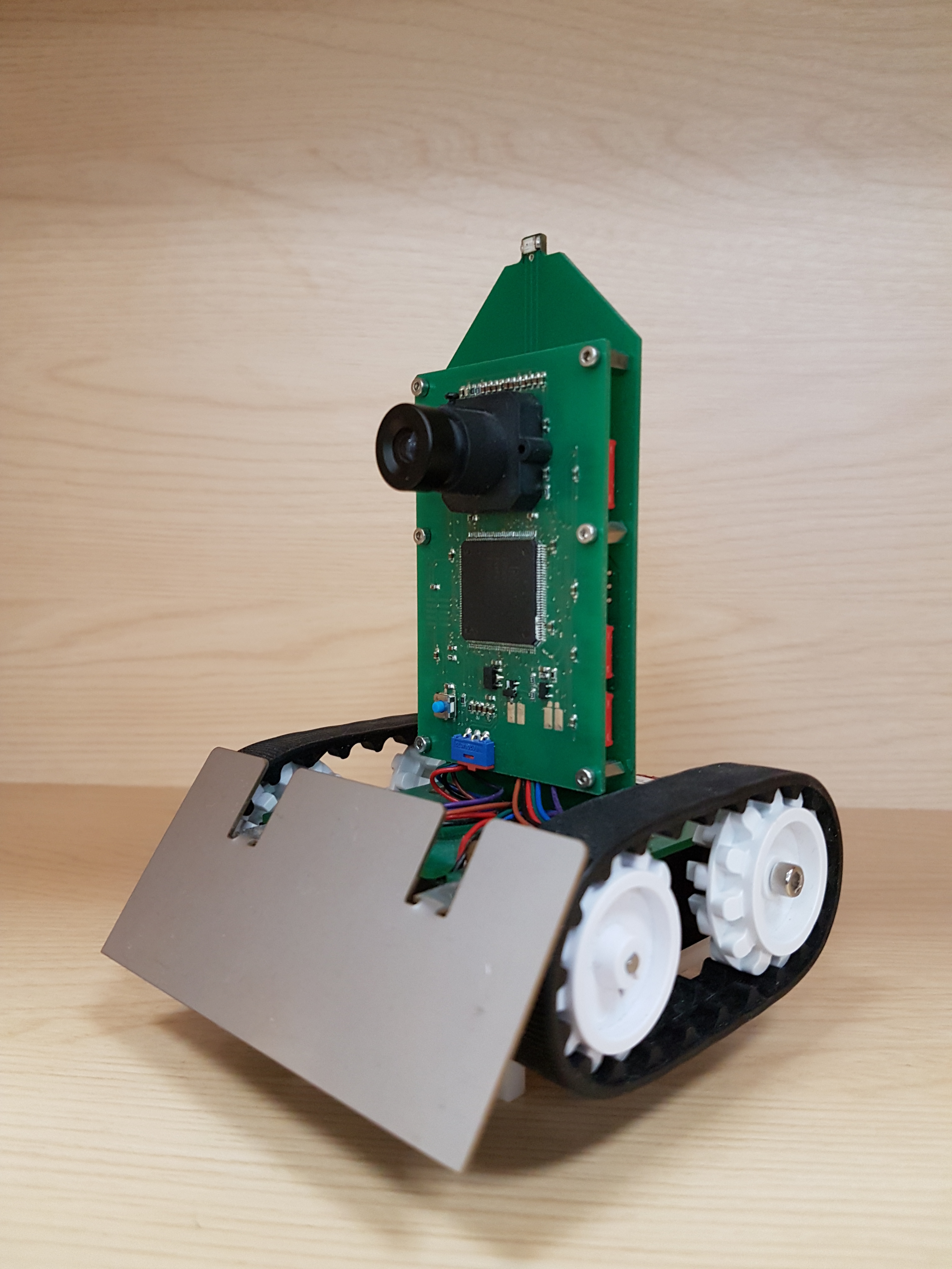
The Robot
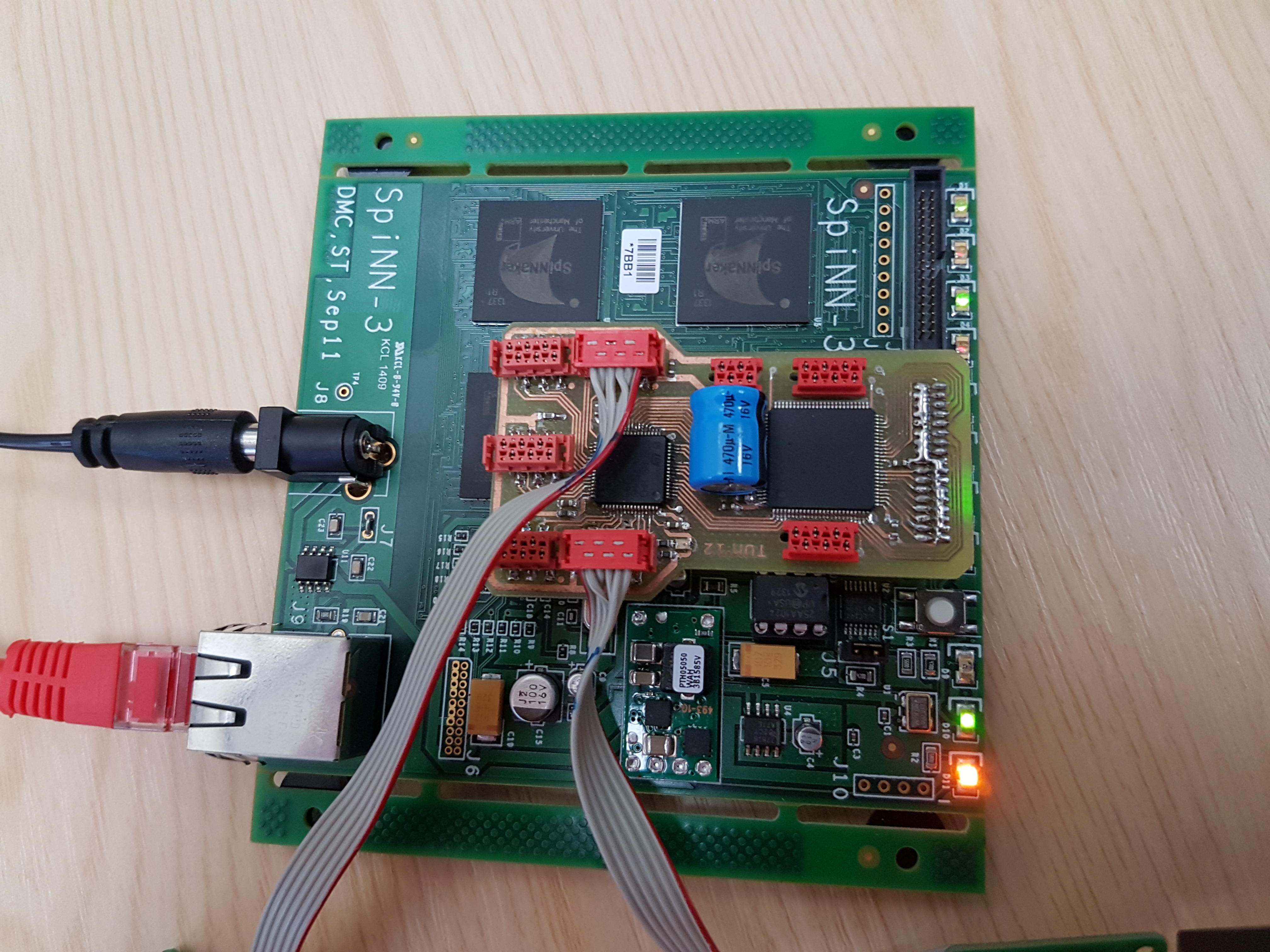
The wifi connector for the SpiNNaker machine
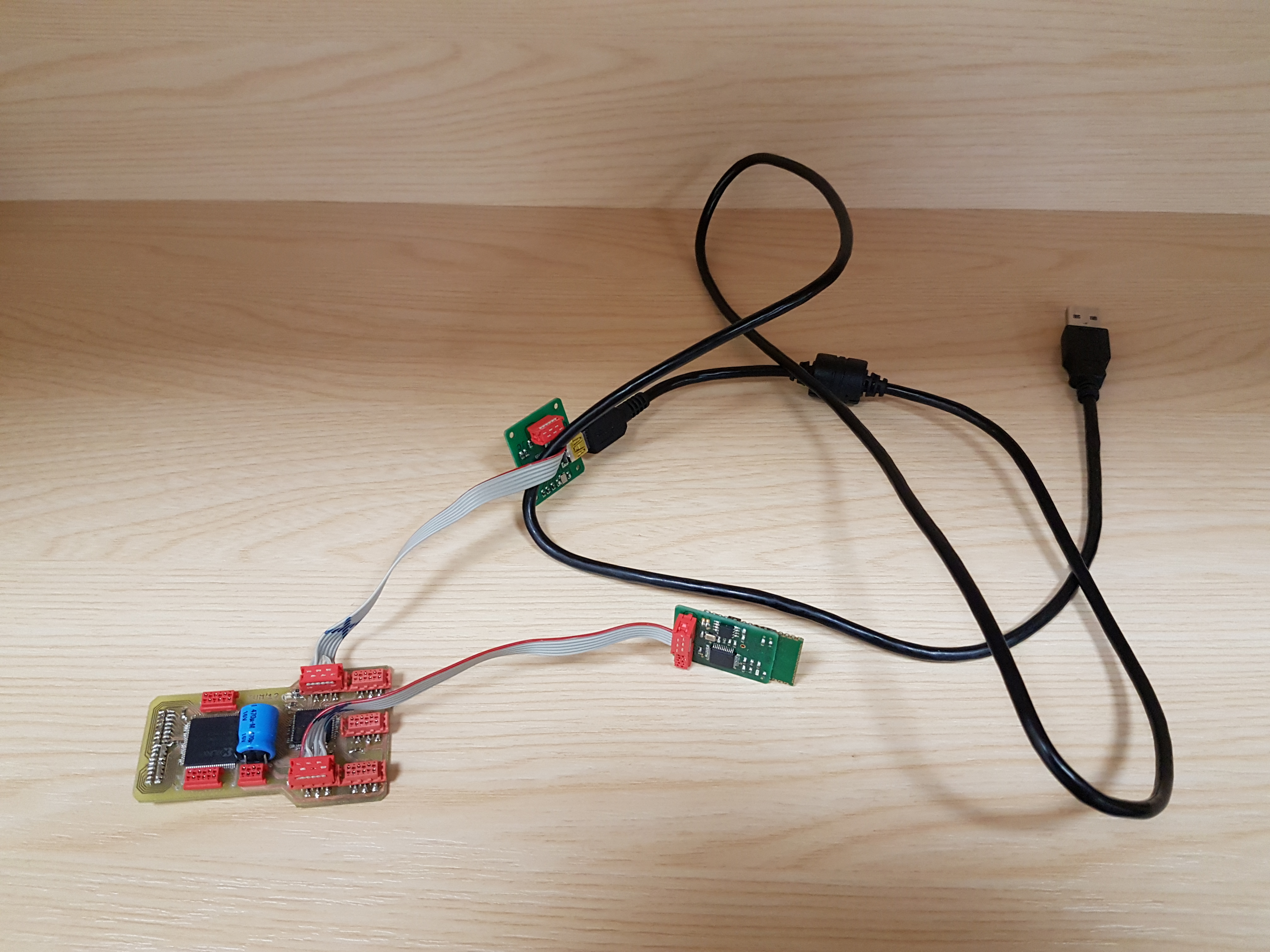
To use the SpiNNaker board wifi adaptor, you must first plug the usb connection into something to provide it with power.
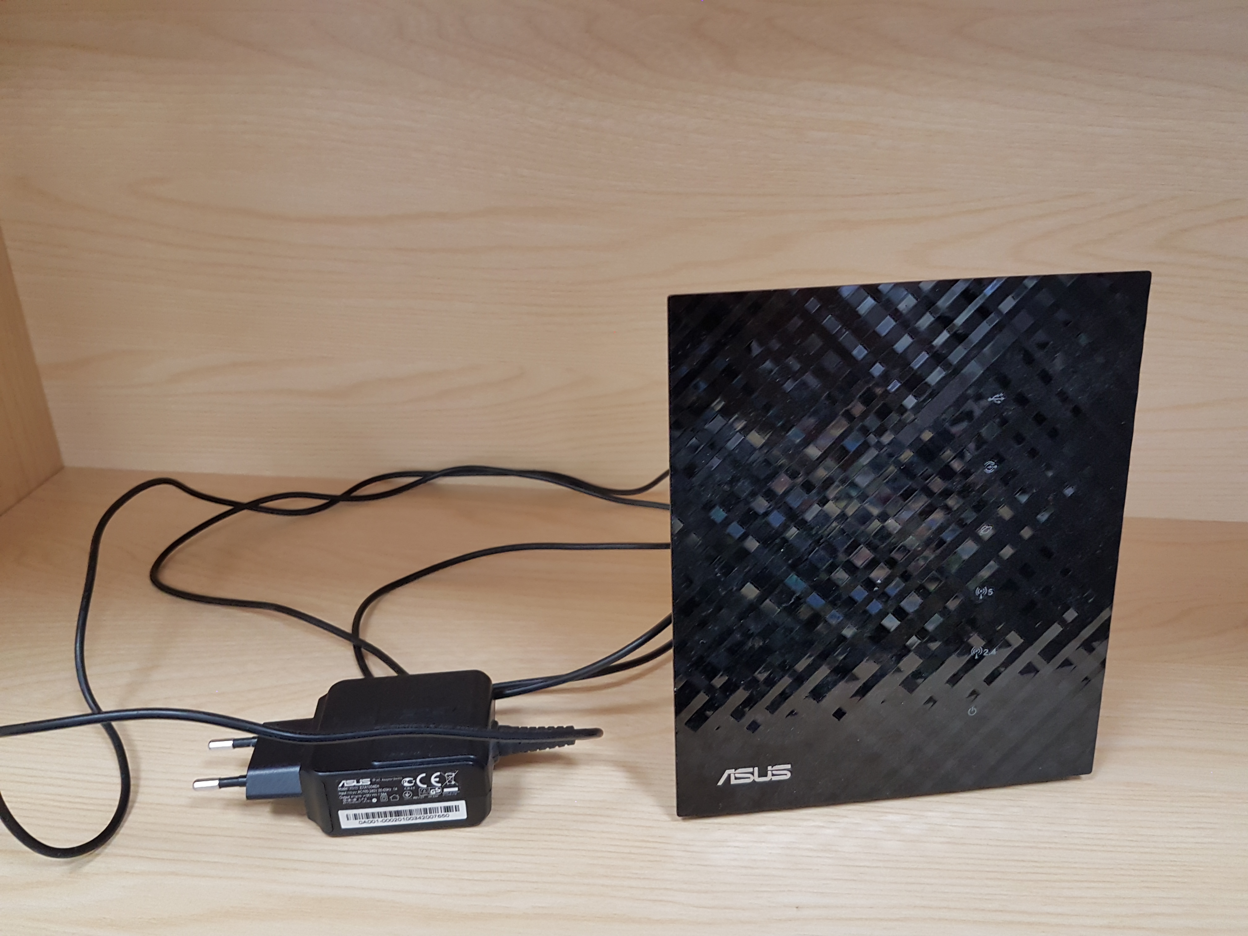
The wifi access point that is used to relay between the push bot and either a host machine or the wifi connector.
The PushBot is a robotic platform developed by Technische Universität München.
Hardware Overview
Robot Features
- 2 tracks, each controlled by 2 wheels.
- A silicon retina.
- A laser.
- A LED.
Control Systems
The robot can be connected to a SpiNNaker machine through 2 interfaces. * It can go through the SpiNNaker link connector via the WiFi connector provided above. * It can be connected to SpiNNaker via the access point (shown above) indirectly via a host machine and using the SpiNNaker Software Stack.
SpiNNaker-Facing API
The API for the robot has changed and is now defined in the following google document:
https://docs.google.com/document/d/1lJ2t5ISbdJpgHs7oGCI9pG10y2xzKz2hoclRX5WocLM/pub
(Alternatively, a copy was made on 22-09-14 in the event that the above link should die: http://pastebin.com/HC5GPs0n)
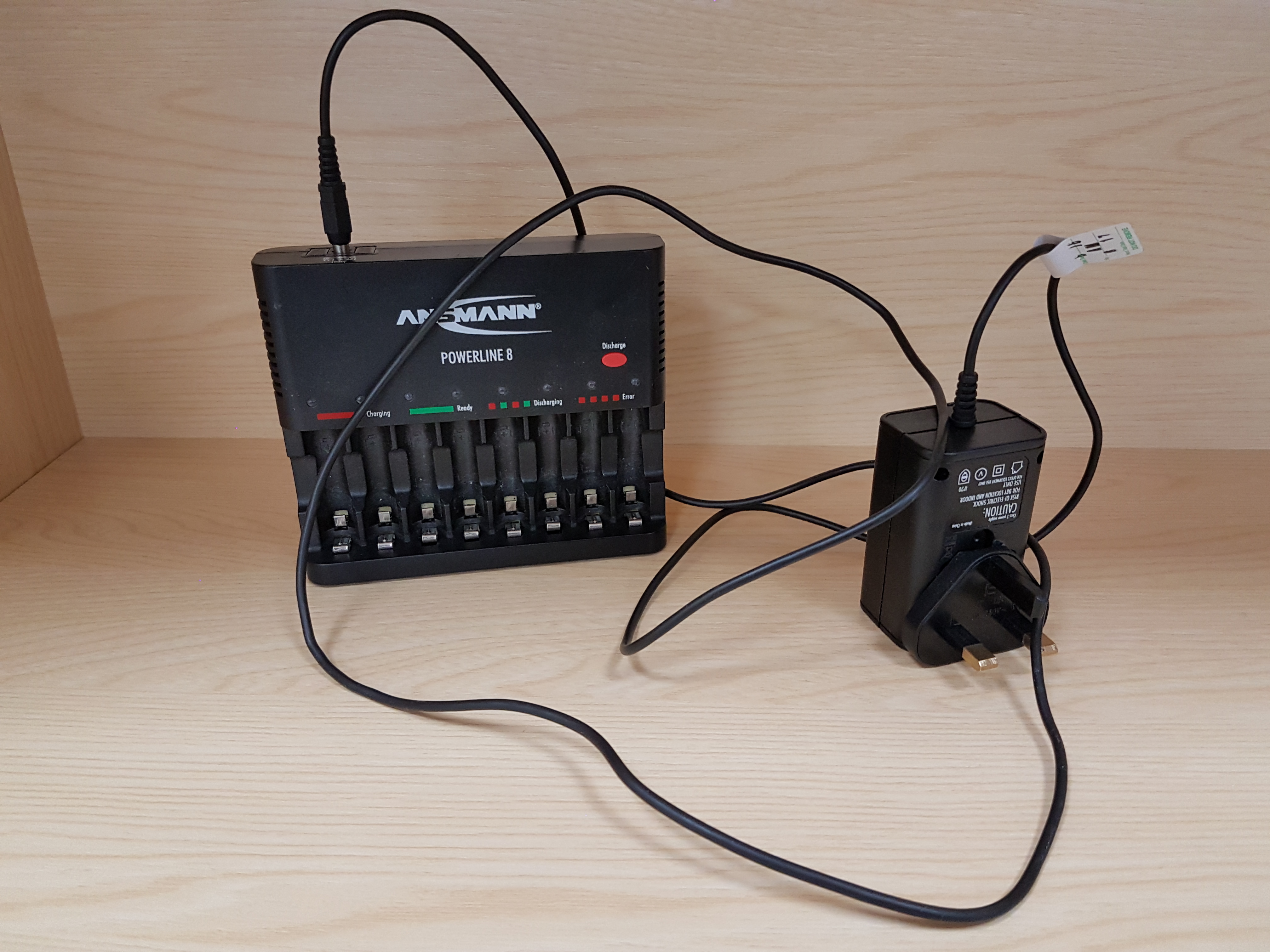
Charging
The robot has 4 AA batteries which are located below:
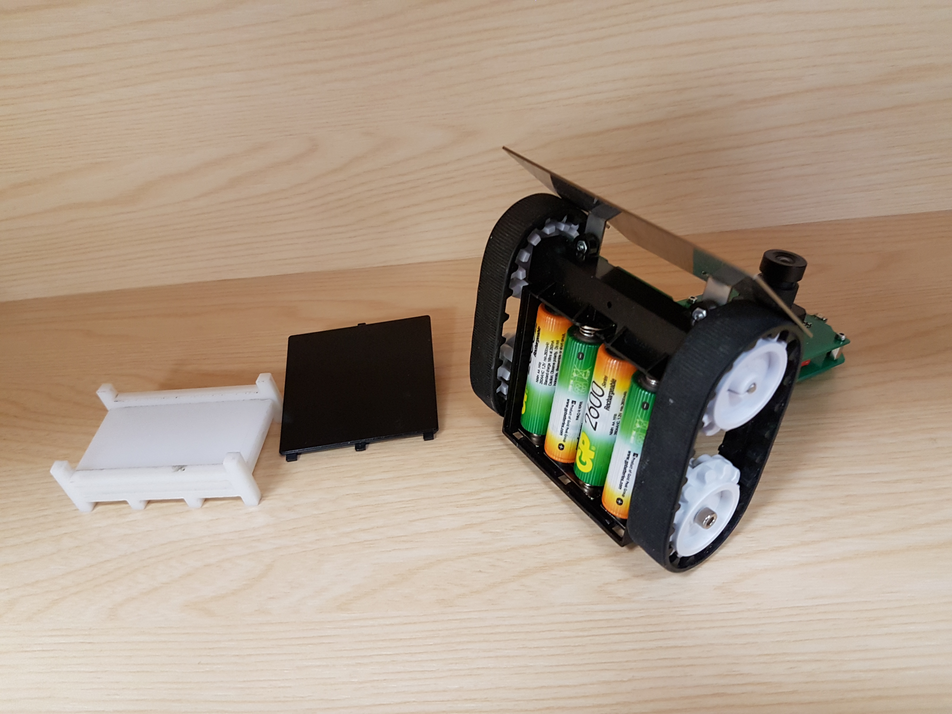
There is a provided battery charger as shown below:
Wifi Access Point
The robot’s wifi interface consists of a WiFi access point to which the pushbot communicates with regardless of the connection type for SpiNNaker. The network details are below. But for simplicity, the password to log into the access point is rpo45trkrfgpoloektr45poael
2.4 GHz
SSID: NSTrobots_2.4GHz
wireless mode: b/g/n mixed
b/g Protection: auto
channel bandwidth: 20/40 MHz
channel: auto
extension channel: above
authentication method: wpa2-personal
wpa encryption: aes
wpa key: rpo45trkrfgpoloektr45poael
network key rotation level: 3600
tx power adjustment: 100
region code: europe (channels 1-13)

Guest AP: off
Bridge: AP only, Channel auto
Wireless MAC filter: empty
Radius Setting: empty
5.0 GHz
SSID: NSTrobots_5GHz
mode: a/n
rest see above
LAN IP: 10.162.177.1 Subnet: 255.255.255.0
DHCP Server
	Domain Name: tu-muenchen.de
	IP Pool Start: 10.162.177.175
	IP Pool End: 10.162.177.249
	Lease Time: 86400
	Default GW: 10.162.177.254therobot

	DNS 1: 10.156.33.53
	DNS 2: 129.187.5.1

	Manual Assignment:
		00:23:A7:01:04:89	10.162.177.20	RedPineMiniSPI00
		00:23:A7:01:08:2E	10.162.177.21	RedPineMiniSPI01
		00:23:A7:01:08:17	10.162.177.22	RedPineMiniSPI02
		00:23:A7:1B:C7:D9	10.162.177.30	RedPineSPIEval
		00:23:A7:1B:C9:77	10.162.177.31	RedPineSPI01
		00:23:A7:1B:C9:34	10.162.177.32	RedPineSPI02
		00:23:A7:1D:C7:8E	10.162.177.40	RedPineSmall00
		00:23:A7:1D:88:EB	10.162.177.41	RedPineSmall01
		00:23:A7:1F:0E:FD	10.162.177.42	RedPineSmall02
		00:23:A7:1D:8B:27	10.162.177.43	RedPineSmallSPI03
		00:23:A7:1D:5B:60	10.162.177.44	RedPineSmallSPI04
		00:23:A7:1D:8A:8E	10.162.177.45	RedPineSmallSPI05
		00:23:A7:1D:5A:E7	10.162.177.50	OmniRob7-ROB-TOP
		00:23:A7:1B:C7:94	10.162.177.51	OmniRob7-000
		00:23:A7:1D:8A:95	10.162.177.53	OmniRob7-120
		00:23:A7:1D:5A:F5	10.162.177.55	OmniRob7-240
		00:01:36:1D:D7:13	10.162.177.60	Rovio00
		00:01:36:22:84:74	10.162.177.61	Rovio01
		00:23:A7:1D:58:4A	10.162.177.62	OmniRob62
		00:23:A7:1D:5A:DB	10.162.177.63	OmniRob63
		00:23:A7:1F:0F:94	10.162.177.64	OmniRob64
		00:23:A7:1D:36:9C	10.162.177.65	OmniRob65
		00:23:A7:1D:36:80	10.162.177.66	OmniRob66
		00:23:A7:00:14:11	10.162.177.130	RedPine5GHzSPI0
		00:23:A7:00:9C:B1	10.162.177.131	RedPine5GHzSPI1
		00:23:A7:00:14:1D	10.162.177.132	RedPine5GHzSPI2
		00:23:A7:00:9B:C9	10.162.177.133	RedPine5GHzSPI3
		00:23:A7:00:14:13	10.162.177.134	RedPine5GHzSPI4
		00:23:A7:00:9C:A7	10.162.177.135	RedPine5GHzSPI5
		00:23:A7:00:9B:D2	10.162.177.136	RedPine5GHzSPI6
		00:23:A7:00:9A:30	10.162.177.137	RedPine5GHzSPI7
		00:23:A7:00:9B:4A	10.162.177.138	RedPine5GHzSPI8
		4C:E6:76:F7:DE:35	10.162.177.59	SpOmniBot

Route
	use dhcp routes: yes
	enable static routes: yes
	static routes:
		0.0.0.0	0.0.0.0	10.162.177.254	303	LAN

IPTV
	off
Firewall Disabled
Login nst/nst
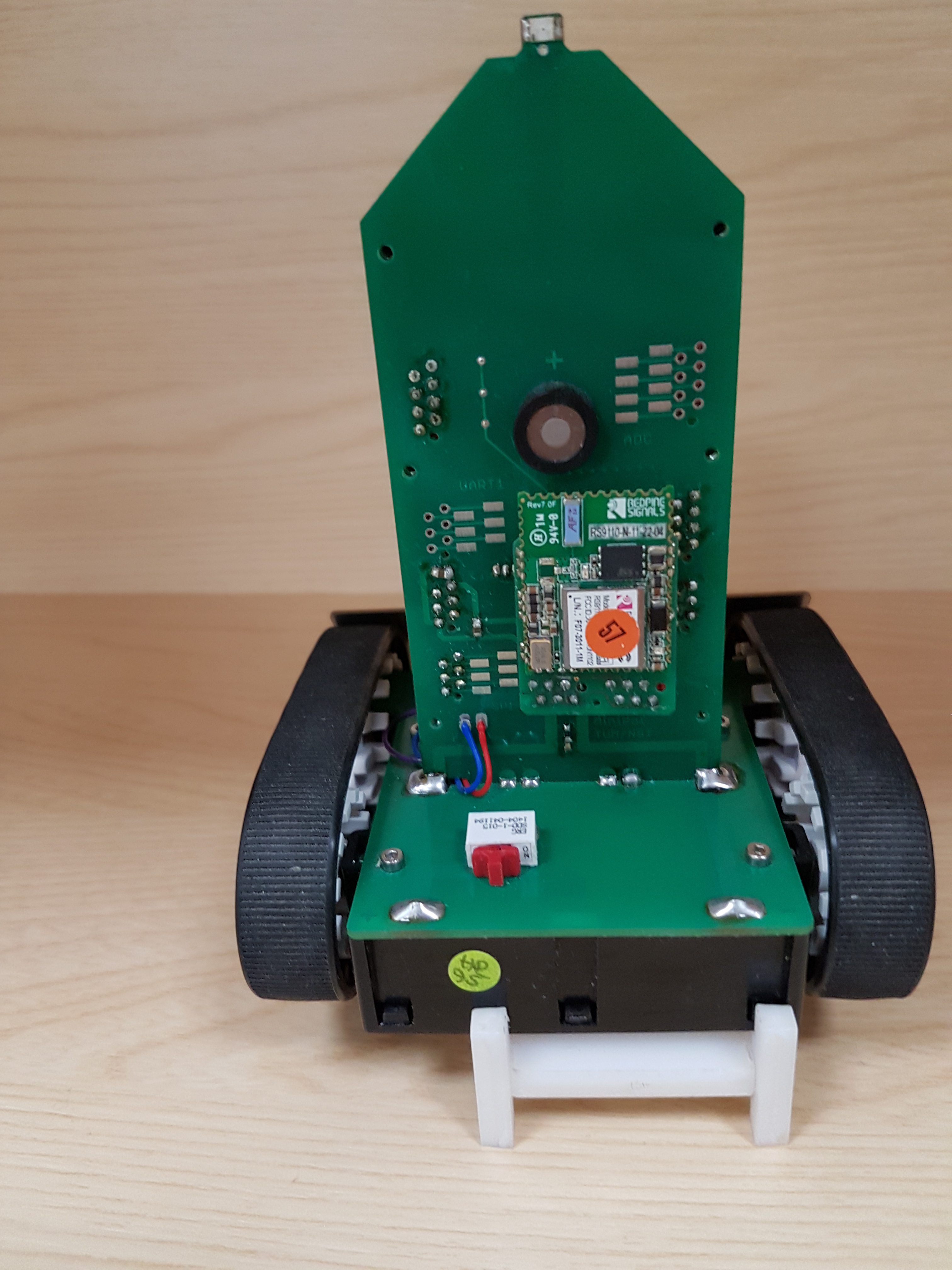
robot ip addresses
The IP of the pushbot is 10.162.177.XXXXX where XXXXX is the number of the red circle at the back of the push bot. As shown below, where the IP would by 10.162.177.57. The IP of the SpiNNaker link wifi board is 10.162.177.56
Setting your uni machine to communicate with generic 4 chip boards.
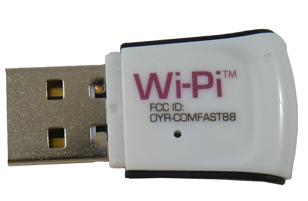
University machines
If you are using a desktop machine and the host configuration, you will need a wifi adaptor, as shown below, to connect to the wifi access point. These can be acquired from central services through the website http://studentnet.cs.manchester.ac.uk/ugt/hardware. The systemw as originally tested with the WiPi adaptor from there.
If you are using a remote profile supported by centeral services, you need to be careful with your configuration to stop your wifi adaptor overwriting your ethernet gateway address. The best option we have found is to plug in a switch between your machine and the ethernet socket, and then wire that to the wifi access point and then do the following commands.
sudo ip addr add 10.162.177.254/24 dev eth0
sudo ip addr add 192.168.240.254/16 dev eth0
Ubuntu machines
-
open a command terminal and enter the following commands.
sudo ip addr add 192.168.240.254/16 dev eth0 ifconfig
if this is successful, you should be able to ping the standard 4 chip board that communicates on ip address 192.168.240.253
Windows machines
- install (WinIPConfig 4.0)[http://www.pkostov.com/wordpress/?p=19}
- turn on WinPIConfig and if message about interface on 0.0.0.0 0.0.0.0 click yes (we currently dont know what that is)
- right click on window labeled “available IP configurations loaded form: . …” and click add new configuration item.
- add the following data: IP_ADDRESS: 10.162.177.254 SUBMASK: 255.255.255.0
- click ok
- right click on window labeled “available IP configurations loaded form: . …” and click add new configuration item.
- add the following data: IP_ADDRESS: 192.168.240.254 SUB_MASK: 255.255.0.0
- click ok
- click on “detailed interface view” and open up tabs till you reach your ethernet adaptor
- right click on ethernet adaptor and click on “add secondary ip address ….”
- select the ip_address 10.162.177.254
- right click on ethernet adaptor and click on “add secondary ip address ….”
- select the ip_address 192.168.240.254
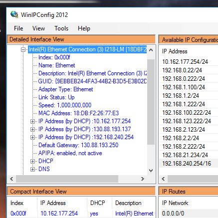
- verify that the ip_addresses exist in your ethernet adaptor (see below)
- open up a command prompt and once powering up the pushbot and the spinnaker_link device ping the machines through the below commands: ping 10.162.177.56 ping 10.162.177.57
connection order for the spinnaker link based protocol to behave
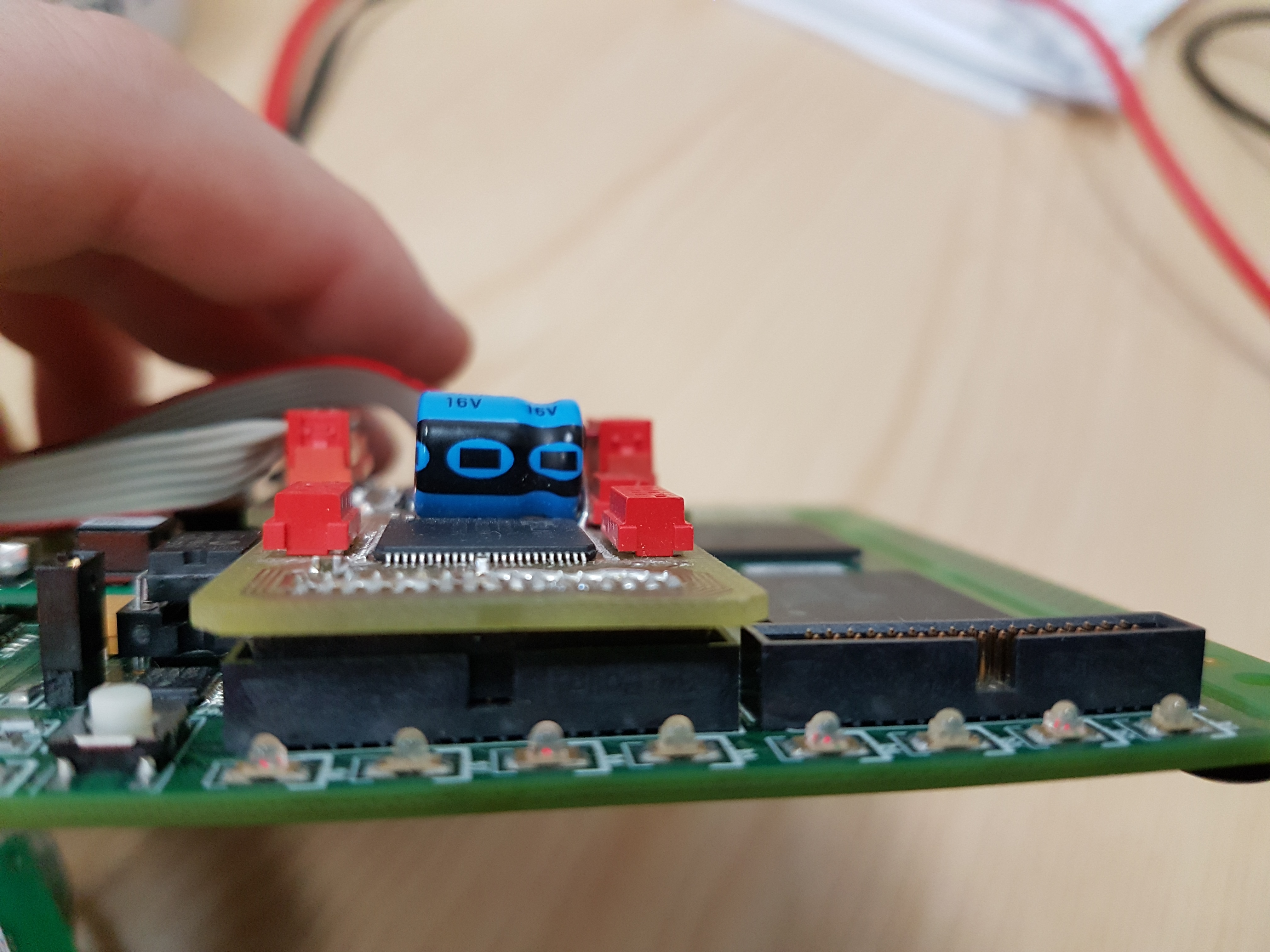
connect the SpiNNaker wifi connector to the 0 SpiNNaker link where the board is hovering over the SpiNNaker chips (as shown below). Be careful to align the pins correctly, otherwise you shall find it wont respond at all
It seems to be a issue that if the components are not connected and powered in a specific order, then communication fails. The successful connection order is below:
-
turn off
- spinnaker board
- wifi adaptor power (usb thing)
- push bot
- turn on push bot and wait for it to connect to wifi (flashing green light) and then ping to verify you can communicate with it
- turn on wifi module (put in usb) wait for flashing green light. ping to verify you can talk to it
- turn on spinnaker board,
- run script.
If this fails to work, try the following (it seems 48 chip vs 4 chip boards have different order for best chance of working):
- turn off all.
- turn on push bot.
- turn on spinnaker board.
- turn on wifi module (put in usb) wait for flashing green light. ping to verify you can talk to it.
connection order for the ethernet link based protocol to behave
- turn off all.
- turn on spinnaker board.
- turn on push bot.
Note: You must ensure that the wifi module is turned off, as only 1 client can talk to the push bot at a time, and it keeps the connection active till client is switched off.