The Robot
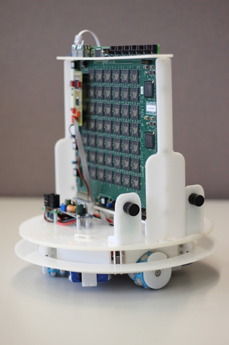
The SpOmnibot is a robotic platform developed by Technische Universität München. You can read more about this in the paper “Real-Time Interface Board for Closed-Loop Robotic Tasks on the SpiNNaker Neural Computing System” (Christian Denk, Francisco Llobet-Blandino, Francesco Galluppi, Luis A. Plana, Steve Furber, Jörg Conradt) in Artificial Neural Networks and Machine Learning ICANN 2013.
Hardware Overview
Robot Features
- Three omniwheels driven by DC(?) motors
- Encoders to detect wheel rotation for each motor
- Multi-point bump-sensor
- Two silicon retinas
- SpiNNaker board mount
- Separate batteries for the robot and for SpiNNaker
- TODO: and some other things…
Control Systems
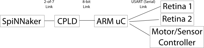
The robot is connected to the SpiNNaker board via a spinnaker 2-of-7 asynchronous link connected to the otherwise unused South-west link on chip (0,0).
The robot is controlled by a small SpiNNaker interface board which contains a CPLD and an ARM microcontroller. The CPLD essentially translates between the 2-of-7 signaling used by SpiNNaker and a simple 9-bit binary interface (8 bits of data with extra signals for end-of-packet, req and ack) used by the microcontroller.
The microcontroller communicates with the retinas and the robot’s motor controllers and other sensors via serial connections and exposes these peripherals via a multicast packet interface.
Here is a very crude picture:
SpiNNaker-Facing API
The API for the robot has changed and is now defined in the following google document:
https://docs.google.com/document/d/1lJ2t5ISbdJpgHs7oGCI9pG10y2xzKz2hoclRX5WocLM/pub
(Alternatively, a copy was made on 22-09-14 in the event that the above link should die: http://pastebin.com/HC5GPs0n)
Charging
The robot has two sets of batteries:
- Omnibot motors:
- LiPo charging mode, 2 cells in series 7.4V (2~3 hours).
- use 2xbanana to “power” plug cable.
- connect red/black banana plugs in charger output sockets.
- connect “power” plug to socket next to robot power switch.
- SpiNNaker board:
- LiPo balanced mode, 3 cells in series 11.1V (10~12 hours).
- use (2xbanana + 4-pin plug) to 6-pin plug cable.
- connect red/black banana plugs in charger output sockets.
- connect 4-pin balance plug in 3-cell balance charging socket.
- connect 6-pin plug to small board on robot, next to large batteries.
Wifi Access Point
The robot’s wifi interface consists of a WiFi access point to which the SpiNNaker board is attached via Ethernet. The network details are as follows:
SSID: NSTrobots1 pass: robospinn
The IP of the SpiNNaker board is 172.16.1.2. The access point will assign your machine an IP in the same network upon connection (172.16.1.x).
Attachments
- robotSpiNNakerInterfaceBoard.zip - Source code for the SpiNNakerRobot Microcontroller Interface
- main.jed - programming file for the cpld on the interface board
- spomnibot_cpld_code.tgz - Source code for the cpld on the interface board
- spinInterface.axf.zip - binary code for the uC interface
- omnibot.h - MC based communication protocol
- SpinLink34-RobotIO.pdf - uC board schematics